
CURRENTLY VIEWING |
||||||
|
DEPTH OF FIELD USING RAYTRACING
Using raytracing techniques to simulate depth of field
|
||||||
 |
||||||
|
@
programming > computer graphics
|
||||||
|
SECTION MENU
|
||||||
This is a program written in openGL to simulate depth-of-field (DOF) effect using raytracing. User will define 3 parameters to specify the DOF look, namely the aperture size (which determines how blur the objects out of focus are), the focal length (which determines the z-distance in the view space which objects will be in focus) and the number of rays (which determines the quality of the blur).
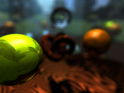
DOF render with: Focal Length = 2, Aperture Size = 64, Rays = 16
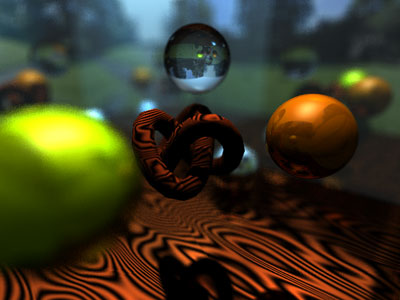
DOF render with: Focal Length = 5, Aperture Size = 128, Rays = 16
An imaginary focal plane F is first defined behind the image plane. A ray is then cast from the eye through the current pixel to be rendered. The intersection point between this ray and F is the focal point P.
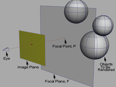
Focal point P is found by intersecting the current ray with focal plane F
A square grid of length m (determined by the aperture size set by user) is placed on top of the current pixel and n rays are shot out from this grid to P, using stratified sampling. These DOF rays originate from the sampled grid point in image space and not from the eye. The results collected from these rays are blended to get the final color of the pixel to be rendered.
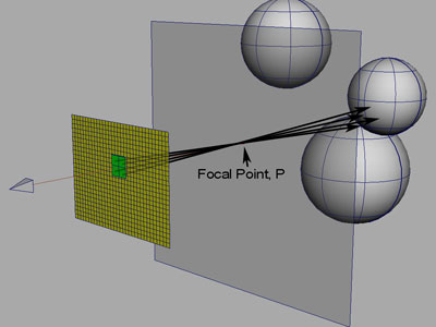
n rays are shot out from the newly placed grid, through the focal point P
I used similar triangles to find out where P is at for the current ray. We first find:
- d: The perpendicular distance from eye to image plane
- d’: The distance from the eye to the pixel in question
The intersection point of the current ray (due to the current pixel to be rendered) with the focal plane is calculated as
![]()
where e is the eye’s world position, v is the unit vector from eye to current pixel and f is the focal length as specified by the user.
Initially I did not jitter the sampling points on the grid and the result obtain had visible bands due to uniform sampling. It is the visual justification that we should use random sampling instead.
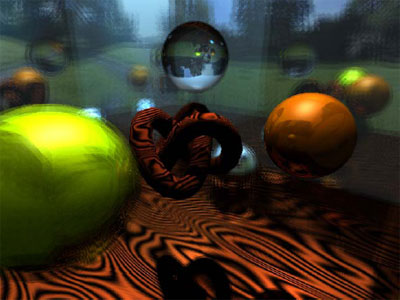
Undesired banded appearance due to uniform sampling
Note: As this is part of a group project, this DOF effect is created by modifying a distributed raytracer done by my groupmate Neo Jiet Shern.

Hi,
I am trying to implement this method to generate DOF in my RayTracer.
I tried this way:
- Take a 3×3 window around the current_pixel,
- then did stratified sampling in that 3x3_window
- Throw rays (16 rays) from these sample points to the point P (as mentioned in the article).
- Take the average color of all these 16 rays and put the value in the current_pixel
What I see is not DOF but something like a FOG or a lot of noise
Can you please clarify more how you managed to do DOF with this method?
I would be grateful if you can reply soon.
Thank you
What you have mentioned seems correct. Maybe you could try to vary some of the variables like the focal length and aperture size. Perhaps some of these variables are not set correctly for your particular scene.
Also, check your implementation with just one ray per pixel first, just to be sure that the general raytracing codes are correct in the first place.
[…] general understanding of Depth of Field came from this article, specifically the diagrams near the bottom. I think I implemented it a little bit differently then […]